About
Notes on a little modding project in which I took apart a tiny remote controlled car and tried to turn it into a self-driving toy with the help of a Raspberry Pi. At another level, observations on the difficulties of seeing behaviour () in a simple embedded system.
I didn't quite get my car to lap my test track the way I hoped, so we'll have to call this is a progress report.
I hope to pick this up again once I've digested the lessons () from this first attempt. There's lots of interesting system and behaviour building questions and related tooling concepts to explore as well.
Introduction
I recently went digging around my archives, taking a look at all the things I did during my studies at Aalto University (2009-2014). At Aalto, I spent a rewarding, if a rather exhausting five years completing a master's degree in computer science learning about computers, the art of computing, and the infinite landscape of software systems.
In much of my coursework, the focus was primarily on the powerful theory at play — the abstract and the general — but for balance, there were many hands-on projects and assignments of all kinds. One of the most memorable of all my courses was an introduction to embedded systems, where my fellow CS students and I learned about the ways in which software can interact with the physical world. As a software specialist, this was pretty much my only exposure to this truly magical domain.
(At Aalto, there's a whole distinct discipline dedicated to the study of this domain: automation and systems technology. The practitioners of this field specialise in building embedded systems, robots, control systems and all kinds of gadgets that bridge the gap between analog electronics and digital computing. And then of course you have the true electrical engineers, etc.)
The project in my embedded systems class was to write software for a remote controlled (RC) car that had been modified to run, not from signals generated by a handheld controller unit, but from a microprocessor that had been embedded inside the car. We would write software on desktop computers, and then compile the software down to bytecode that the car's microprocessor could understand. The task at hand was to build system software that was able to monitor the car's sensors, to manipulate the actuators that operated the car, and then, ultimately, to drive around a track without supervision.
There was a race at the end, and I believe my team did rather well.
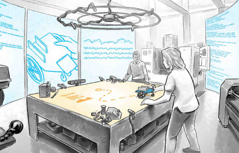
Fast forward to 2020, and my head is full of Bret Victor's ideas and in particular that tantalising notion of the Seeing Space. There's something here that gives me no rest, but I have no means of exploring it. The Big Idea is sufficiently fuzzy, that it's impossible to grasp directly, and so I'm compelled to try and build things in order to get closer.
With the arrival of the Covid-19 lockdown and some extra quality time to spend indoors, it was time to revisit the fun I had with the embedded car project back in uni days and to see what I could learn about system behaviour.
Hardware is hard
I don't think I've owned any kind of RC toy since I was a little kid. I vaguely remember getting an RC car as a gift, possibly one shared with my brother (either officially or unofficially), and really enjoying driving it around. Maybe the car fell down the stairs, and never quite recovered, or maybe I simply moved on to other toys. I believe the car did end up getting disassembled at some point, at least to an extent where I could see what was inside.
My childhood RC car felt large, though it is possible that I was simply rather small myself. The car we used at Aalto was moderately sized and crazy fast, but with the custom built sensor buffer, it felt a little unwieldy as well. For this project, I wanted to go for something a little bit smaller, something to fit in a London flat.
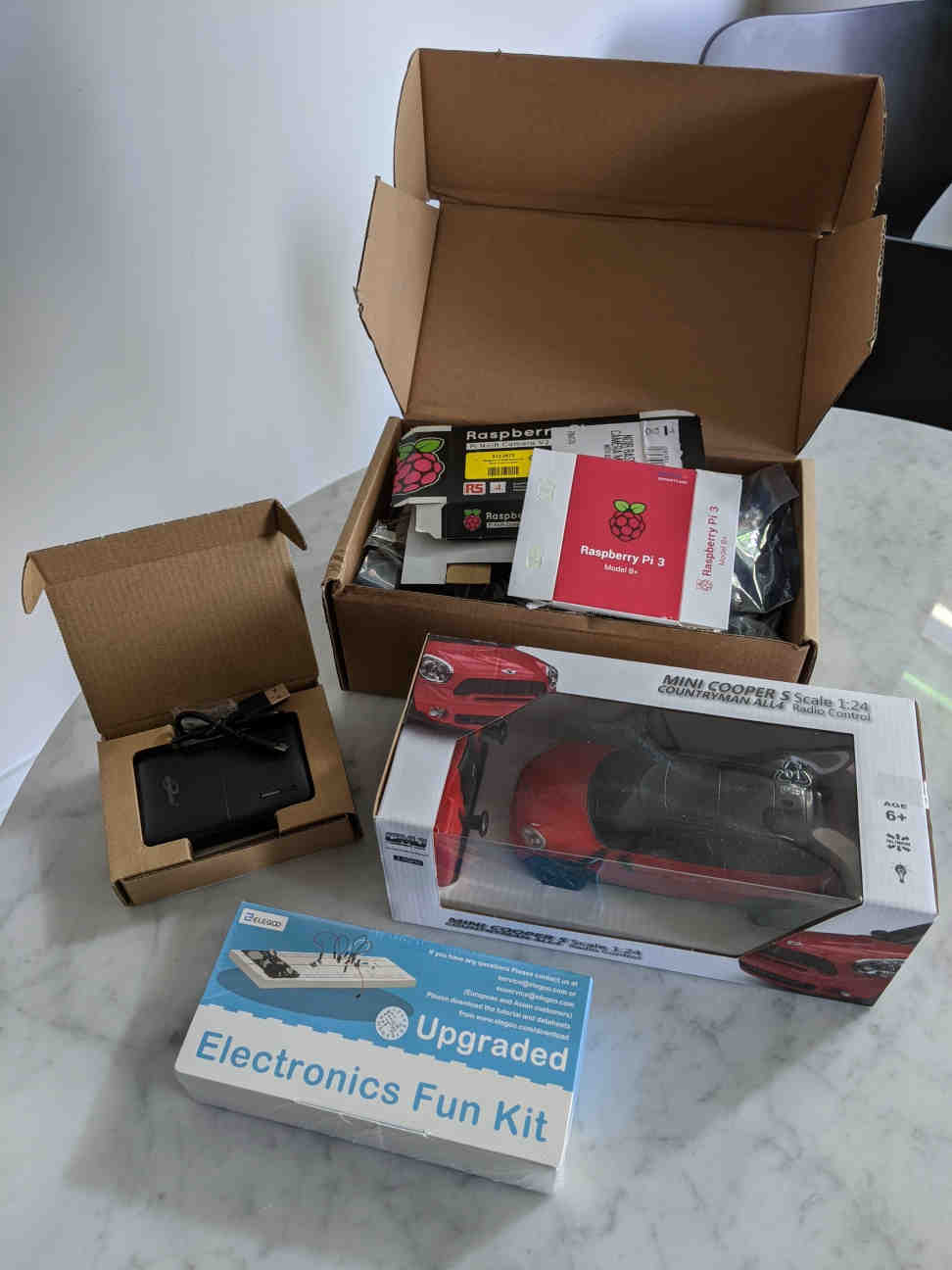
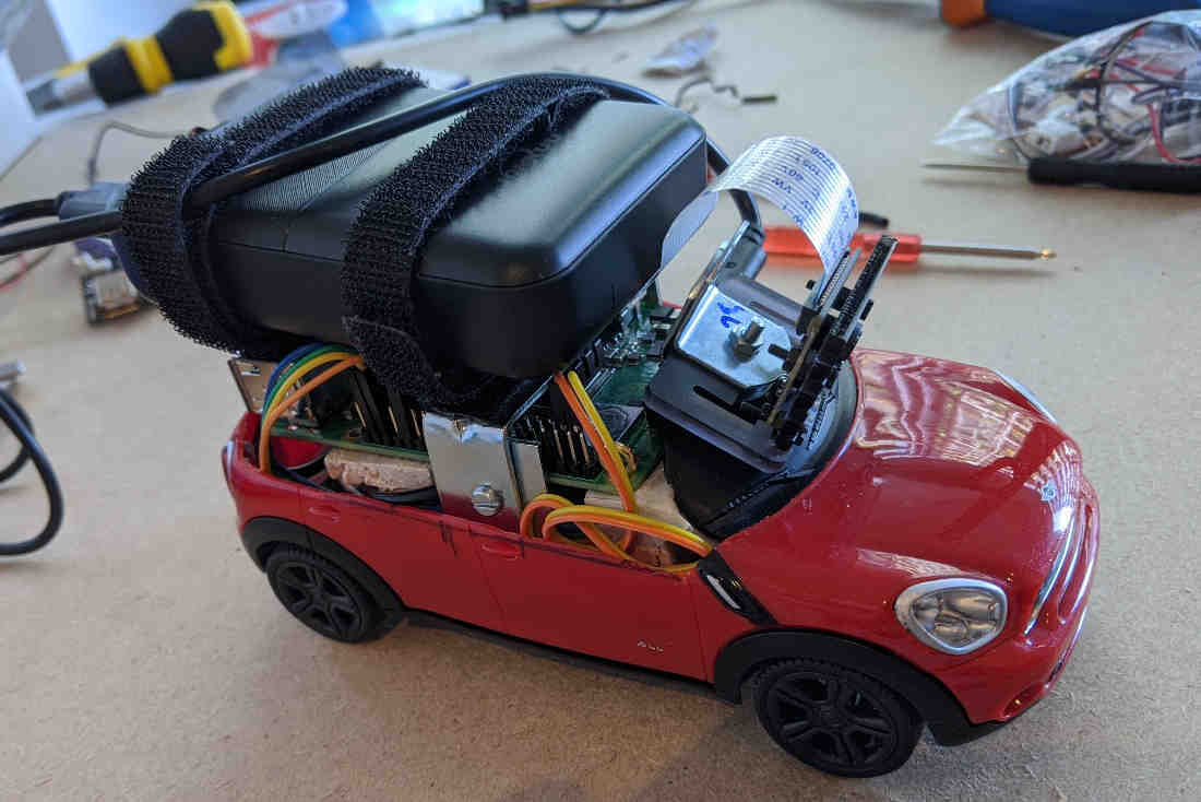
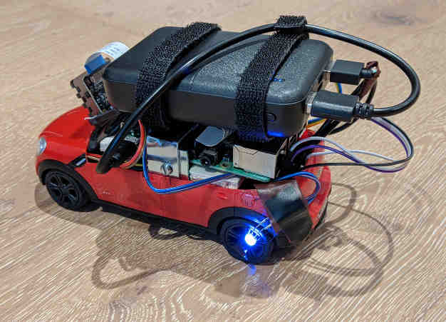
After some looking, I found a nice looking cheapo one with the British Mini branding, and so I settled on the idea of building my very own Mini Driver. I also picked up a basic battery for my build, and a starter electronics kit for spare parts. From a previous project, I brought in a Rasperry Pi 3B+ with all kinds of peripherals.
Unboxing the car
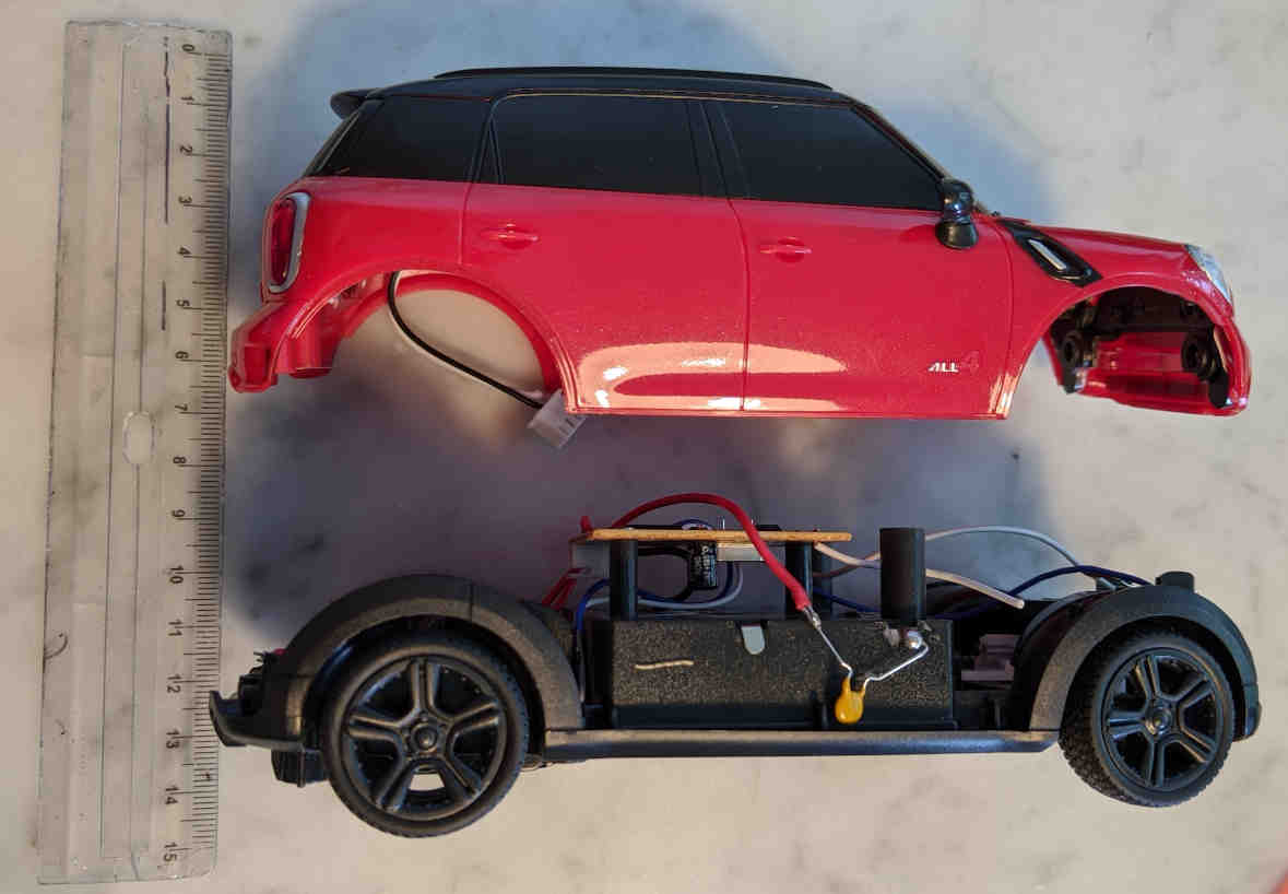
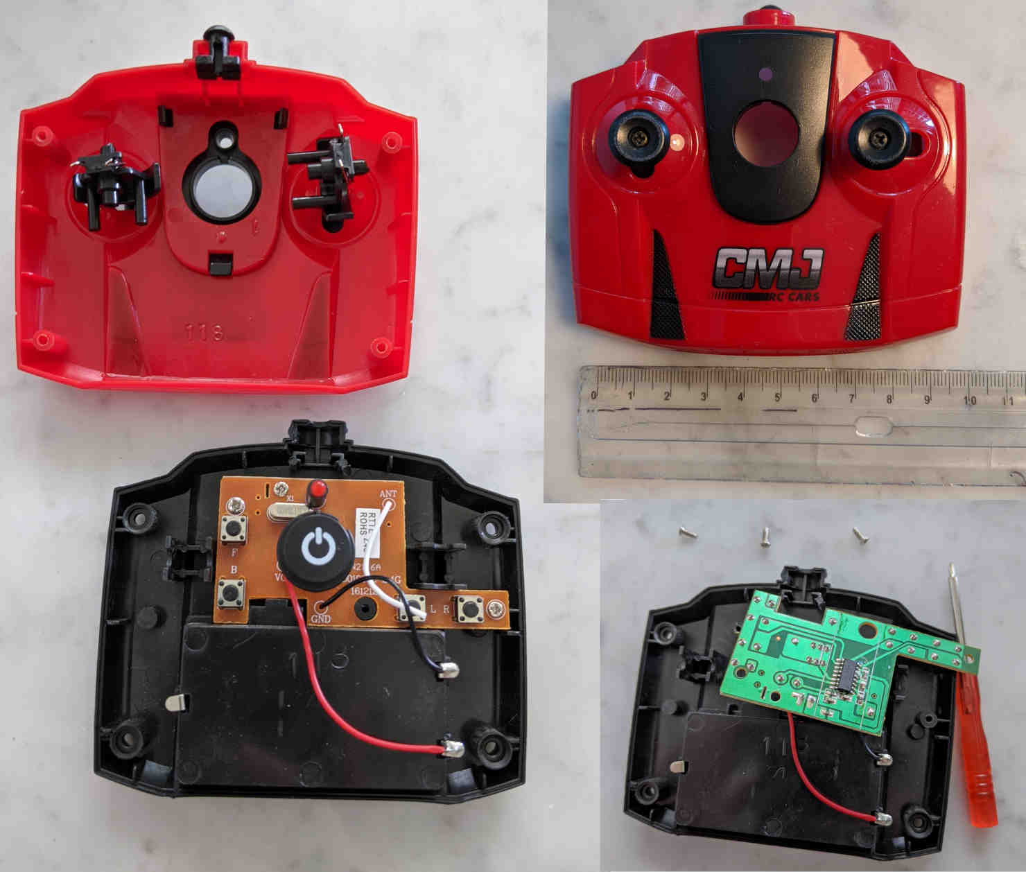
I immediately liked the small size of the car, and for the price, I found the build quality to be okay. The high-frequency radio chip used in the controller meant that the antennas could be very short, just flimsy wires of a few centimeters. There's barely anything there in the original handheld controller. They didn't even bother with a faux old school antenna on the controller.
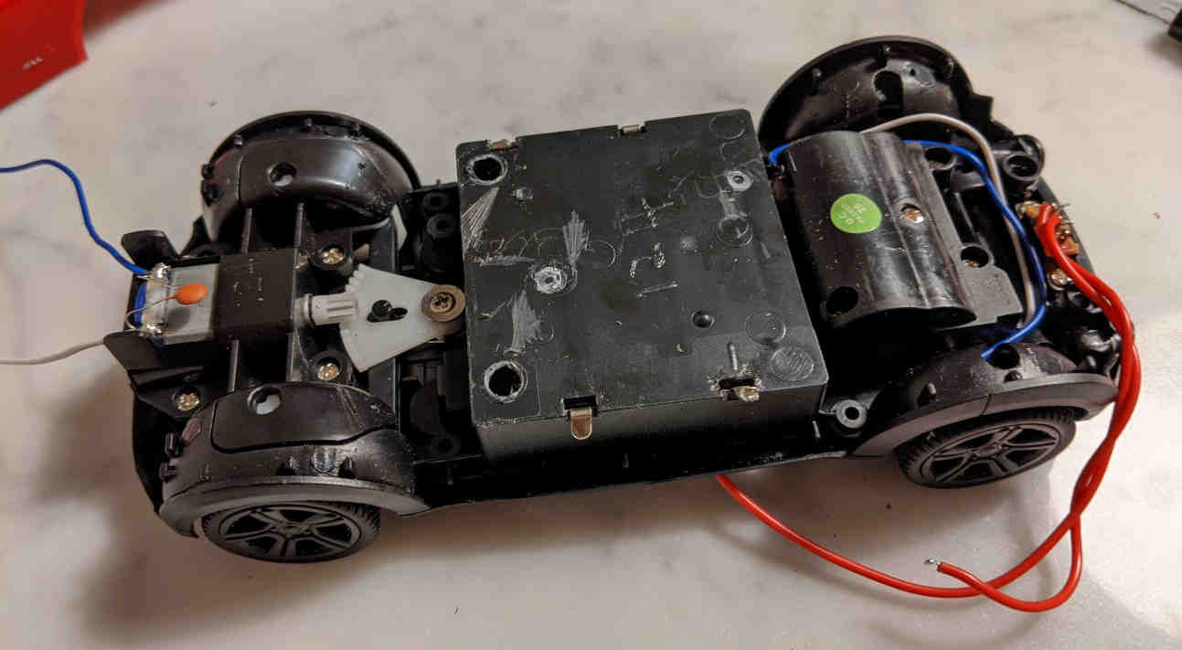
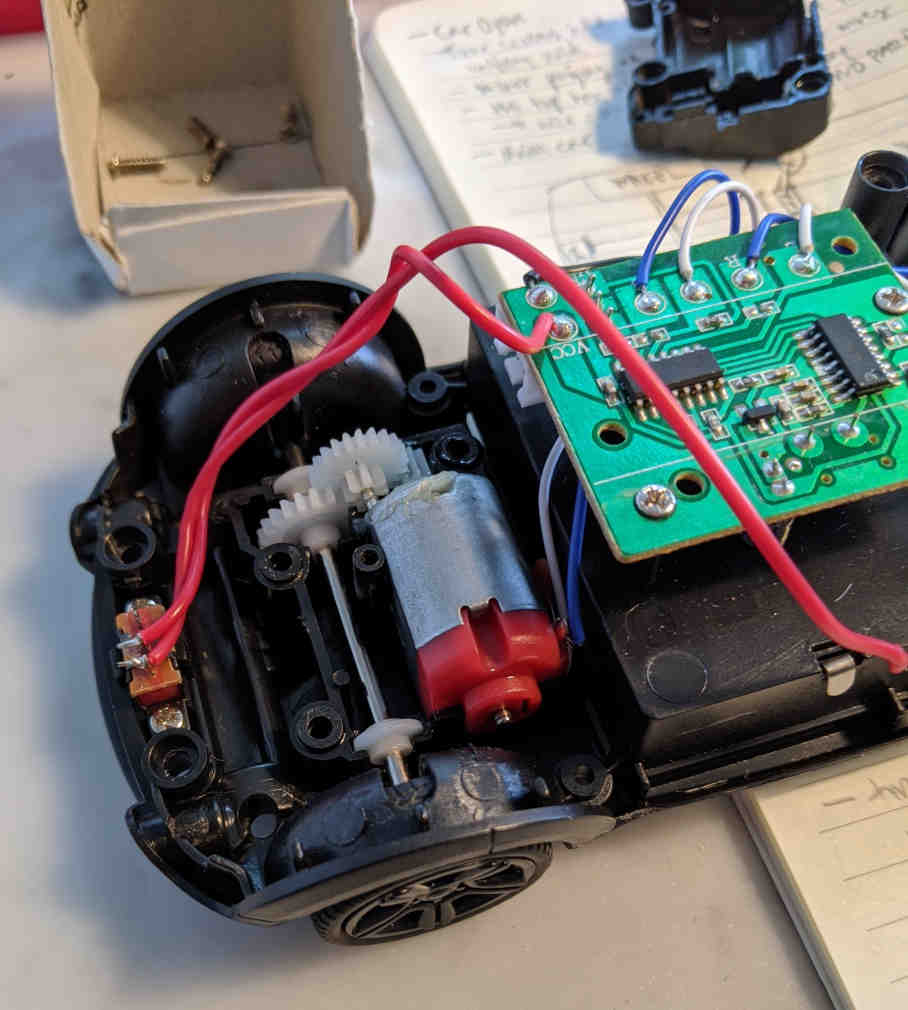
The car is powered by two DC motors — one for throttle, one for steering. The motors proved way overpowered for indoor use, especially with such coarse inputs. I had the car skidding on my living room floor with barely a touch of the controls. The motors ran forwards and back, as one would expect even from a cheap toy like this.
There was a bit of a learning curve to steering, as the default steering angles were really shallow. The car took its sweet time and space to turn 180 degrees, and perhaps even more worringly was far from regular in doing so. I'm sure the dust on the floor didn' help with grip.
Both the throttle and the steering mechanism work on an unbuffered all-or-nothing principle. The motors rev as fast as they can whenever they spin. There also a spring assist to re-centre the steering on idle. In other words, pressing left on the controller slams the tyres in one extreme steering angle, while pressing right slams the tyres in the opposite extreme. Without any input, the spring automatically re-aligns the tyres with the car chassis. There is even a little hardware tab under the car to align the tyres with respect to the spring.
Together the overpowered engine and the crunchy steering led me to develop a kind of flicking-based driving touch, where one doesn't so much press as tickle the buttons. Instead of a sustained control signal, I found that the temperate driver will aim to produce a sequence of taps to generate short pulses that achieve the desired gradual shifts in acceleration and steering, effectively modulating two engines simultaneously.
We never see the internal state. However, we do have a good vantage point to see the external behaviour — the stuff that matters. And yet, from the outside, we can only change behaviour within the parameter space allowed by the available controls. To build new behaviour, to fundamentally change the behaviour of the system, we have nothing to work with, we see nothing. The system is a black box.
Overall, I quite enjoyed testing out the car as delivered. Thinking about driving from the third person point of view is engaging: it is a fun toy. However, I was also keen to get started with modding.
Taking the car apart
The diminutive frame of the car proved a challenge to work with. My original plan was to hide all the electronics inside the body of the car, to keep as much of the original appearance as possible, but that was not meant to be. With better tools I might have been able to carve out more space inside the car, but I was keen to get going with the meat of the project, so I decided to quite literally just cut some corners.
Once I started modifying the car for self-driving, I had no use for the remote control mechanism, put it was still useful to figure out how the default configuration works. Turns out that the controller is super simple, as is the circuit on the other end.
In the controller, there are two sets of toggle buttons, each set under a simple, mechanical rocking switch. In other words, the inputs are digital ones and zeros, closed and open circuits. There's a clock chip that gives a steady timing signal, and a 2.4GHz transmitter with a short antenna. The main chip on the controller has the label N17 48A.
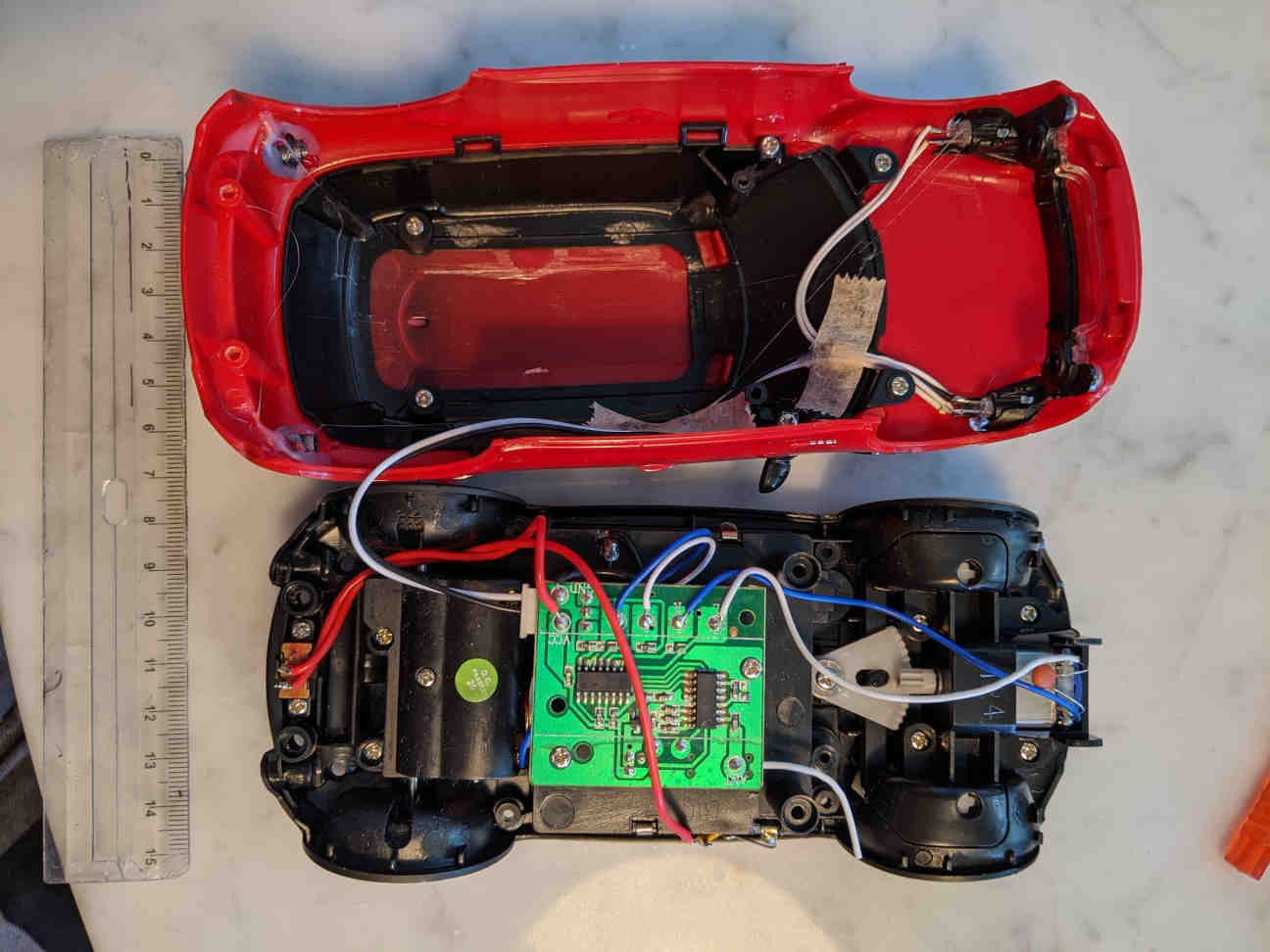
Inside the car, there's a receiver chip with an antenna similar to the controller. The output from the receiver is plugged into a motor driver chip that controls both of the little DC motors. When the axle of the front motor turns, a radial gear system transfers the spinning motion into linear motion perpendicular to the orientation of the car. This motion moves the tyres, steering the car. The motor at the back, enclosed in a lubricated housing, is in charge of the car's acceleration, spinning the rear wheels either forwards or backwards.
The controller and the car are "paired" using simple handshake protocol. The instruction leaflet says to turn on the controller first and then the car second. When you press the big button on the controller, (I'm guessing) it starts broadcasting a wake signal, which the car knows to listen for. When the car hears the controller, it gives out an audible bleep sound and you are ready to go.
Embedded in the plastic at the front of the car's body, there's a pair of LED lights wired up so that they are powered up only when the car is accelerating.
The handheld controller is powered by two 1.5V AA batteries, with the car itself being equipped with three in series for a 4.5V total.
Modding
I had a Raspberry Pi 3 B+ lying around from a previous project, so I resolved to use that as the brain for my car. It's a capable little computer with plenty of general purpose I/O pins with which I could control the car. My Pi doesn't draw that much power, but was still able to run quite an involved driving system, in partially interpreted Python. That said, it wasn't at all difficult to exhaust the computing resources available on the Pi.
Importantly there's a WiFi chip on the Pi, so I was able to access, modify and monitor the system by connecting in over the wireless network. I pinned a network address (IP) to the adapter on the PI, so in my local network I could always reach it from the same address. I remoted in both through Secure Shell (SSH) and a full graphical remote client/server setup via VNC.
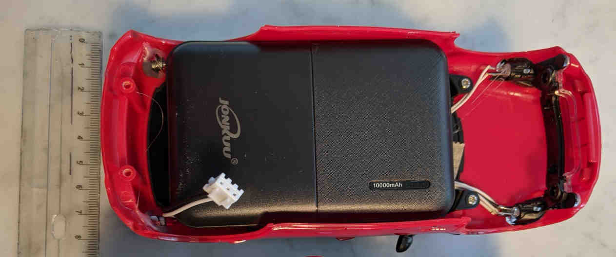
I got a proper rechargeable battery, because I didn't want to run the Pi off of primary cells. After checking out the specs of the Pi, I concluded that any modern portable power bank with a USB output of 5V and some amps should be just fine. I got a basic 10000mAh battery which worked great, giving me a few hours of driving and iterative Pi development time. The battery was compact, but not quite as slim as I'd hoped, and I soon realised that I would have to abandon my plan of having all or even most of the magic out of sight inside the car.
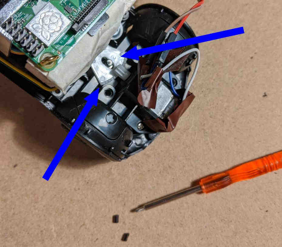
I needed to clear more room inside the car, so the existing circuitry in the car had to go. I carefully de-soldered the thin wires connecting the original control circuit to the motors, as well as the links to the battery case and the LED lights at the front of the car. With what can only be described as "the wrong tools", I then pried away some of the plastic scaffolding that held the original circuit in place. Even with all of these hardware hacks, there just wasn't enough room inside the car to make it all work.
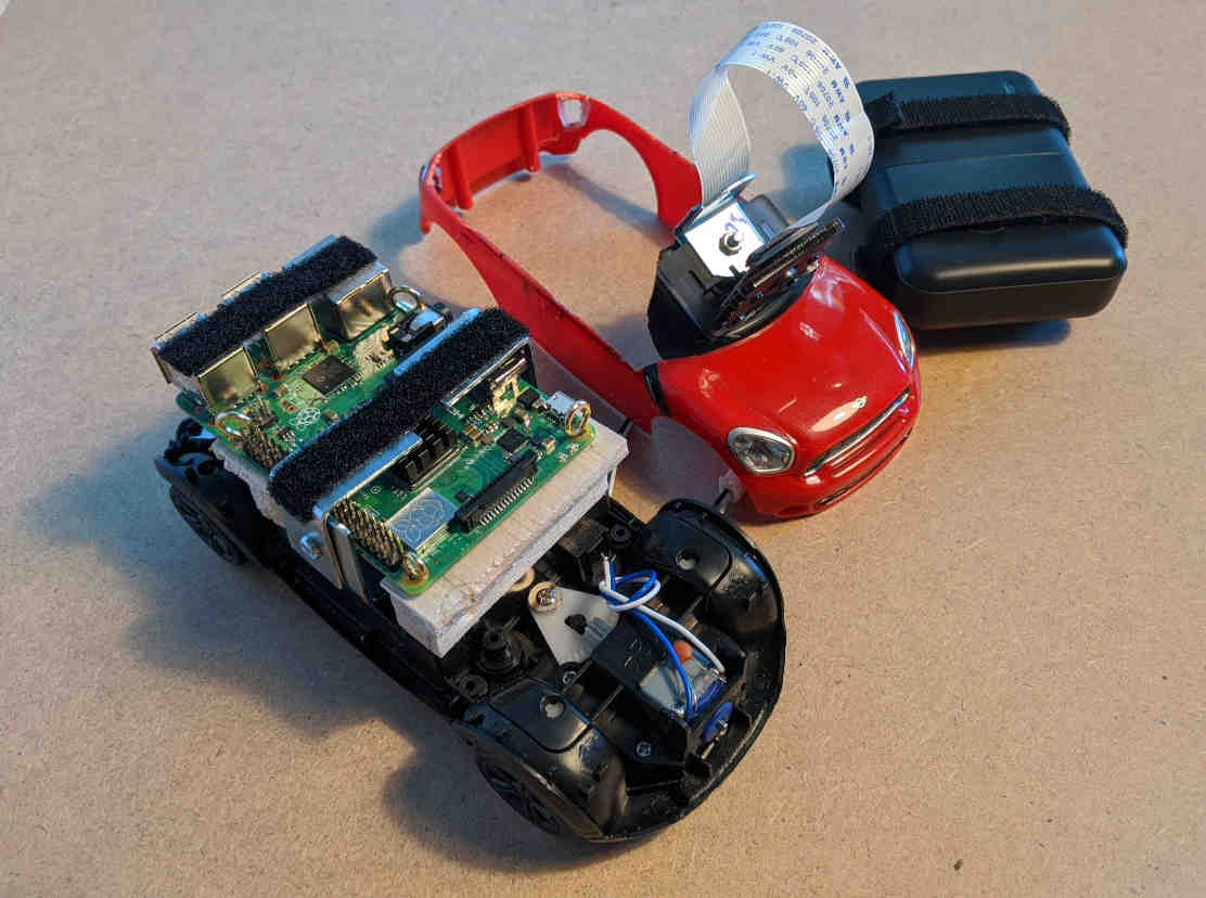
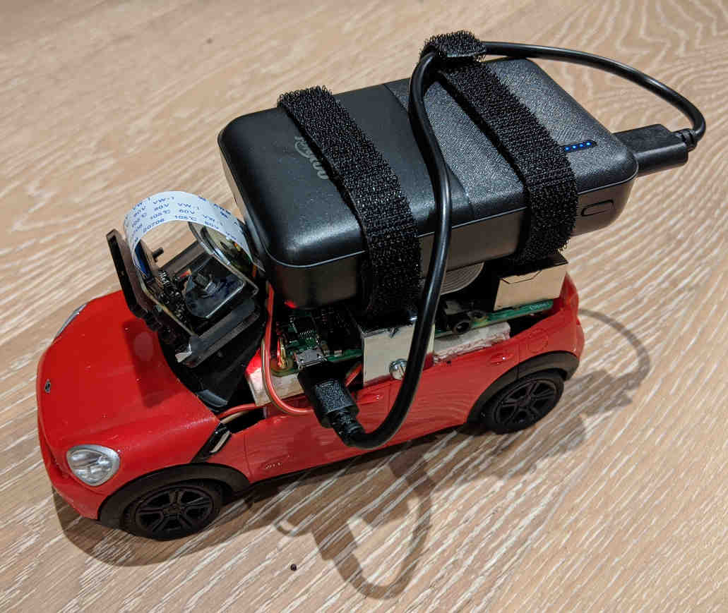
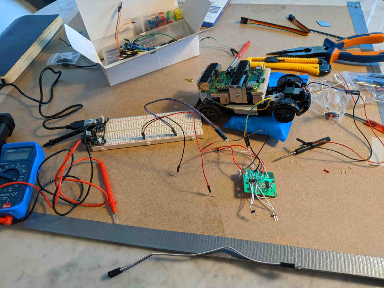
Ultimately, I decided to go for convenience rather than appearance, and so I ended up cutting away the whole top half of the car. I flipped the battery on top of the Pi with the help of some angle brackets and select pieces of lightweight crafting balsa wood I had at hand from a previous project.
As a finishing touch, I rewired the LEDs on the Pi so I could control them separately through pins on the Pi. I managed to blow up one of my kit LEDs by wiring it directly to the 5V circuit. It had been a while since I had done any electronics, so I was happy to blow up one of the LEDs instead of the main circuit.
Sensors
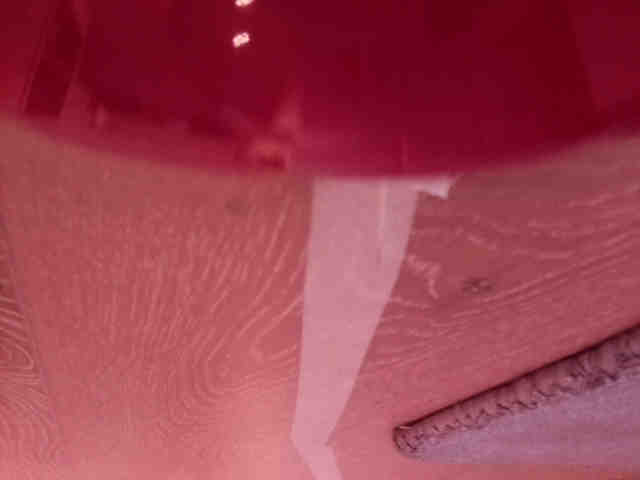
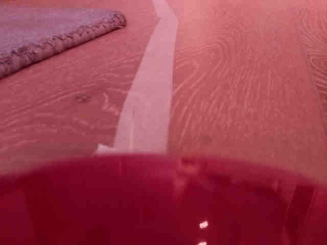
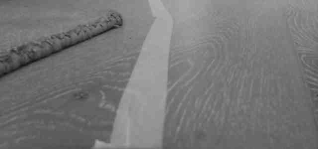
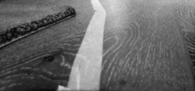
In order to drive around, the driving system needs information about the environment. I wanted to make use of the Pi Camera module I had, and so I bolted it down on the car windshield in an angle in which the camera could see what was in front of the car. This worked fine, though later I made the mistake of selecting white masking tape as my road marker, which the camera sometimes had difficulty distinguishing from my living room flooring. The finish on the flooring picked up enough glare that it interfered with the camera.
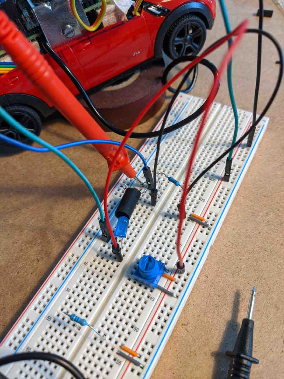
Later, I also experimented with a simple tachometer for measuring car speed, an essential sensor for precise driving control. In my electronics parts kit I happened to have a couple of photoresistors, and I was able to link one up with a bright LED to build a basic tyre revolution counter.
Road and speed sensing is really all you need for basic line following self-driving. The trick is to make both signals simultaneously as accurate and reliable as possible, all the while operating a real time control loop.
Motor control
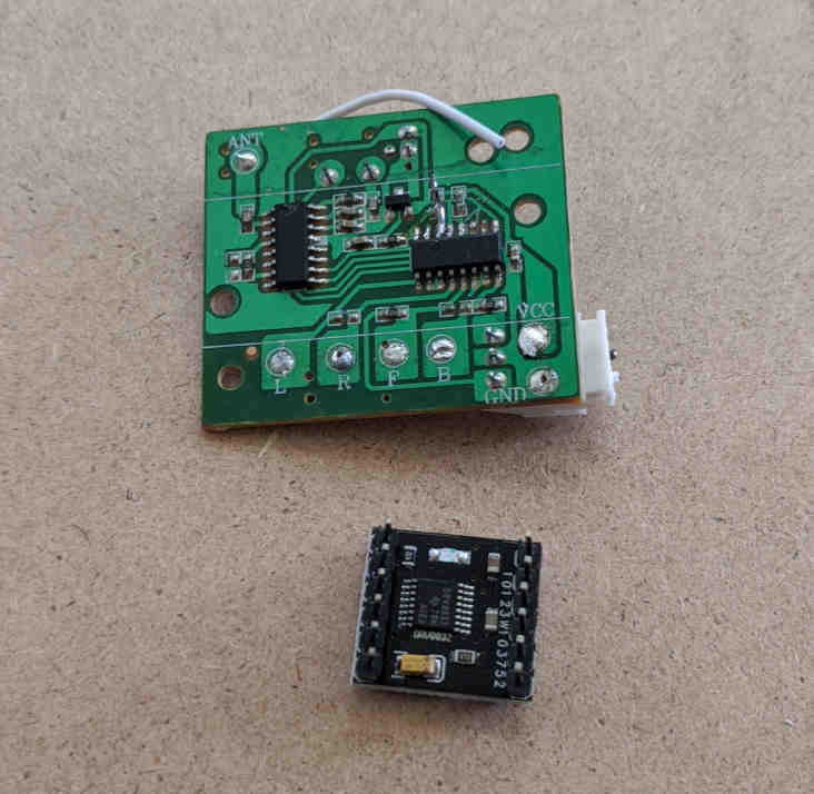
The two DC motors inside the car can both be driven independently in either direction. This is made possible by the motor controller chip, which in the original configuration lives on the same main PCB as the control signal receiver.
Initially, I thought I could drive both motors directly from the IO pins on the Pi, but I learned that this won't work because the motors draw more current from their circuit than the Pi allows the pins to serve — indeed wiring the motors directly on the pins can break the Pi! I gather that it's not so much due to the absolute current the motors draw, but the irregularity of the load: as the motor spins up and down, the change in load is too much for the Pi's circuitry to balance. And this is why you need a dedicated motor driver chip.
I made a heroic attempt to reuse the original motor driver by soldering jumper wires on, but this proved a challenge beyond my skills and tools. After a few attempts, I managed to break off a critical pin from the chip, so I had to get a replacement. I bought a kit of three Texas Instruments DRV8833 motor drivers (a few £ in total) with vastly more accessible pins. I also upgraded from a cheap soldering iron to a Hakko station, which made the whole soldering business much more enjoyable.
With the completed motor driver circuit in hand, I was finally ready to get my car moving. It was fairly simple to hook up the Pi to the motor driver and the driver to the motors, and with the right Python libraries I had the motors quickly up and running.
The DC motors on the car have two terminals: one to spin the motor one way and one for the other direction. In the original circuit they seem to operate on a basic on-off principle, where applying voltage on one of the motor terminals and the ground to the other makes to motor spin as fast as it can in one direction, and swapping the voltage and ground makes the motor scream in the other direction. There is no in-between, or steps between the extremes — other than "no load", which halts the motor.
Granular DC motor control is based on pulse-width modulation (PWM), which is a fancy way of saying that you switch the motor on and off in short, periodic bursts — for the duration of a pulse. The spacing of the signal, the modulation of the pulse width, corresponds to a particular degree of motor power, yielding the control steps missing from the simple on/off scheme. PWM is a standard mechanism, and there are software libraries for the Pi that can do it in any of the Pi's general purpose IO pins.
In my car setup both motors, both pairs of motor terminals, are linked to ouputs on the motor driver board and the driver inputs are wired to the Pi. The motor is then controlled in a relay by sending pulse-width modulated signals to the pins that talk to the motor driver, which then talks the motor. In my programs, I assigned a separate PWM controller on each pin, and then adjusted both controllers simultaneously, per motor.
The PWM parameters on each pin determine how much time, per control cycle, the motor is powered on in the target direction. For the engine, the power going into the motor applies torque on the axle, which then turns the co-centric tyres. The torque provided by the motor, or perhaps the friction between the tyre and and the ground, results in a net force that moves the car along the ground plane.
You need the driver, because the Pi speaks digital, but the motor only understands analog.
(This isn't quite accurate, the difference in signal shape isn't that dramatic, but I think the concept checks out.)
Software is soft
I decided to go with a Python program for the brain, a simple control loop. I figured I could leverage the Python bindings for the OpenCV library for doing the computer vision, and then the python libraries that go with Raspberry Pi for interacting with the hardware. I followed more or less the approach we took in uni, as I recalled it.
The main challenge was building a control algorithm that took sensor readings in, chiefly the camera steering signal, and deciding what state the car's steering and throttle motors should take.
Getting started
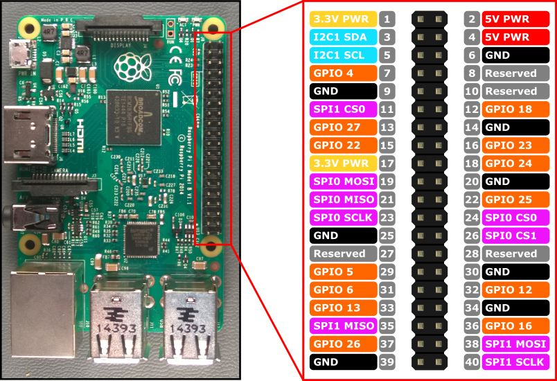
The first thing to try and do with any project like this is to get some LEDs blinking. After studying the Raspberry Pi GPIO pinout for a while, I was able to figure out which pins I can use and how I should address them in the program.
The Python library RPi.GPIO formed the backbone of my driver applications. This not the approach for a proper realtime application, but I wanted to keep things simple and using Python on a Raspbian OS was the quickest way to get something going. How hard can it be to drive two motors at the same time?
After getting my car to blink the LEDs, it was time to wire up the motors and get them going. In playing around with the motors using a breadboard, I realised that the motors run one way when given a ground on one pin and enough voltage on the other, and then reversing the contacts makes the motor drive the other way. Connecting the battery directly made it all work fine, so I figured I could just hook up my Pi directly to the motors and be off to the races. WRONG.
After realising the mistake in my thinking about DC motors, I first tried to make use of the original motor driver that came with car, but in the end I had to get a separate, more manageable motor driver circuit to wire up in my car mod. The replacement motor driver worked like a charm.
As I mentioned earlier, the motor controller is given a pulse-width modulated signal to drive the motors at different speeds. I was able to get his going in minutes using the built-in PWM functionality in the RPi.GPIO library. This library takes duty cycle values in the [0, 100] range per pin, which for two direction of pins I combined to a motor range of [-100, 100], flipping from one pin to the other as the direction changed.
Manual control
The first thing I wanted to do was to regain manual control. In other words, I wanted to drive the car from my laptop, using the WiFi connection between my laptop and the Pi. This meant writing a program that would translate key presses on my laptop keyboard to signals on the pins on the Pi. The right tool for this job turned out to be an old old piece of Unix software, a terminal control library called curses.
Using a GUI on top of a full X environment is of course possible, but I found there to be better uses for the Pis limited resources.
I was able to get manual control going fairly soon after figuring out how to translate curses events into function calls. I could pass the signal to the Pi, but that still left the problem of what exactly should go out into the pins to drive the motors.
With the setup I had, with the car I had, the steering motors really only had three reasonable positions: turn left, go straight, and turn right. It turned out that interim duty cycles for PWM didn't result in any meaningful granularity in steering control (especially before I fixed the steering angles), so I stuck to the extremes. I did experiment with the in-between values, but they mostly just made the motor scream. In short, the valid duty cycles states for the PWM for the steering motor ended up being -100, 0, and 100.
For the throttle, the engine motor, I observed that some degree of finer control was possible, but that in the limited dimensions of my living room, the [-100,-30] and the [30,100] ranges were out of the question because the car would smash into the walls well before I had any chance of reacting. At the same time, any signal under an absolute value of 20 would not even get the car moving. For the car geometry that I was working with, it was also necessary to "step on the gas" when turning slowly, or the car would stall. Similarly holding on to elevated motor power would fire the car down the road once the corner had been cleared.
In other words, I had a fairly short range of reasonable motor values to work with. I set things up so that the up arrow key had the car accelerate and the down arrow decelerate and then reverse. Having the left and right arrows shift the steering state from left to centre to right worked without surprises.
My basic curses setup didn't like it when I held keys down, so for clearer signals, I went for a repeated press control instead. This worked out just fine, but also required some driving training. Having the space bar key kill both motors immediately proved very useful when the car seemed to speed out of control. Because of course you are not controlling the speed of the car: it's acceleration you have control over. Anything smarter than that requires proper control logic.
Another thing that was good to set up early on was a standard pattern for wrapping all my programs in try-catch blocks that cleaned up the GPIO state at both error and normal shutdown, helping to keep the system resources stable and in good condition.
After mastering the arrow controls, I was soon driving like before with the handheld controller. In fact, the stepped granular throttle control alone made my laptop a superior controller to the handheld original.
Steering by computer vision
With basic driving mechanism is working order, it was time to focus on the main self-driving input: the view from the camera.
I had some experience with OpenCV, so I knew it could handle what I was planning on doing. The main challenge was to have it run the processing fast enough in Python on the Pi so that I wouldn't have to go for the C++ api. In the end, the Pi ran my OpenCV processing just fine, even while running all the other control logic on the side.
While image processing and car control were within the resource budget, running X and a VNC session on top of it was too much. My Pi would simply choke up and restart, and would do so more quickly if the battery was a little low. This meant that I couldn't get real time visual telemetry from the car as it was driving. I was able to take periodic snapshots, but that was a far cry from interactive analysis.
I could not see the effect of my changes, I could not see the range of situations my system encountered. I could not see states change over time. I cold not see local behaviour or global behaviour. I was driving blind.
To develop the computer vision algorithm, I followed two approaches: 1) I recorded a good chunk of raw data from the camera, to have something to work with "offline", i.e., outside the car, and 2) I set up a simple viewer app, which I was able to run on the car when it wasn't doing anything else. Together these approaches allowed me to work on the algorithm — the function — that takes as input a raw frame captured from the camera, and maps it onto a numeric value that describes the "road ahead" for the car.
As the steering control is effectively one dimensional, I went with a single number from a [-3,3] range to describe the car's position in relation to the road. It is of course possible to generate far more elaborate signals, but one steering value was enough for decent control back in my uni days.
Computer vision is built on robust image processing that works well enough everywhere in the target domain. In this project I spent a good while mixing and reordering steps in my image processing pipeline in pursuit of a setup that would allow the system to detect the masking tape denoting the road from the background of my living room floor.
The floor and the cheap tape appeared fairly distinct in eyes, and I was hoping that it would be enough for the camera as well, but the difference turned out to be quite a challenge in extreme lighting scenarios (shifting from direct sunlight to moderate shadow). Glare from sunlight proved particularly tricky as it gave both the tape and the floor a rather similar hue and matching saturation and value. My Pi Camera also doesn't have an infrared filter on it (though I think I have it somewhere), so as an extra challenge, my raw input was washed in red.
Why make it harder for yourself just to be able to use cheap tape?
My image processing pipeline worked roughly like so:
With the raw input image processed into a state where the road and the background were separated to a degree, it was time to calculate the signal. My approach was to use a set of masks on top of the image, and then calculate per-mask road coverage, which then in aggregate could be used to compute a single signal value.
For each mask I calculated a coverage value by counting the number of overlapping pixels between the mask and the detected road. These individual per-mask coverage values can then be combined with an independent mask weight pattern that allowed me to emphasise the relative importance of road detection at different parts of the image. After normalising and summing up these weighted coverage values, I was left with a single value that represented the position of the road ahead. I set thing up so that the range was [-3, 3], with zero indicating that most of the road was directly in front of the car.
This setup worked quite well, except when the image processing fell apart in challenging lighting conditions, where parts of the background would incorrectly get detected as road. If the blotches of faux road were large enough, they would skew the aggregation, and produce signal values that were inappropriate for accurate steering, causing the car to miss a turn or veer of a straight path.
Generating a reliable signal with a simple function requires reliable inputs. With unreliable inputs, the function has to be wicked smart.
Cruise control
With a basic steering signal generator in place, it was time to think about throttle control.
Given the limited control range of the engine, I went for a cruise control scheme, where the idea is to have the car go gently around the track at a fairly constant velocity. Velocity is the parameter I want to control, but I only have access to acceleration — and fairly indirect access at that. For accurate control, it was necessary to establish an independent velocity signal.
Calculus is a powerful tool for studying continuous change. In theory, one could record and calculate the current state of a system from a series of indirect point measurements. In reality, the world is messy and fuzzy, and where you are and where you should be do not line up. It's much easier and more useful to directly measure the state of the system, to witness behaviour, and then react accordingly.
Powerful control is built on immediate feedback.
In this project I experimented with automated throttle control based on measuring car speed using a separate tachometer circuit. Additionally, I also briefly considered throttle control based simply on the steering signal.
A tachometer is an instrument for measuring the rotational speed of an object, such as a tyre. There are many types of tachometers, but the main idea is to count the number of times rotation markers of some kind are detected by a sensor. In the context of the car, using nothing but a little algebra, it's possible to establish a reasonable estimate for linear velocity from the frequency with which the tyre completes revolutions.
In the basic tacho I put together the left back tyre is sandwiched in between a photoresistor and light soure. The configuration is set up so that light pulses, photons, register only as they pass through the gaps between the tyre spokes. The photoresistor is part of a circuit that gains and loses resistance based on how light shines on the resistor.
As the resistance of the resistor changes, voltage across the whole circuit fluctuates, including the voltage at the control pin on the Pi. A large enough of a change on the pin will trigger a hardware interrupt in the operating system kernel, which can then be passed to userland software. The rate at which these interrupts arrive into the car control system can be used to estimate the speed at which the tyre is turning, a proxy for the velocity of the car.
Here again, many great libraries and APIs exist to abstract all of this away, so that all I had to do in my car driving app was to set up a handler that is called whenever there is a hardware interrupt on the pin. This way whenever the tyre turns, a function is called in my program.
The simplest interrupt event handler is nothing more than an increment of a counter in the global namespace. As the interrupts come in, a separate process (the main program) periodically reads and resets the counter yielding a measure based on interrupts per period. This of course is a proxy for tyre revolutions per minute, itself a proxy for the car's linear velocity.
I got my light based tachometer to work, more or less, but unfortunately the signal generated by the configuration was even more unreliable than the steering signal from the camera, even after smoothing. The tacho would record no signal once the tyres started moving fast enough, due to the resistor effectively being held in a steady state of saturation. The margin to tune the tacho within this car body configuration simply wasn't there.
Approaching the control problem from a completely different point view, I quickly discovered that because of the requirement for more engine power, more torque, when turning, a simple throttle controller could be built just from the steering signal, perhaps with some bookkeeping. The system would still be driving blind with respect to absolute velocity, but on a bendy track that might not be an issue. In the end, I employed the tacho only as a throttle limiting backup contraint.
Experiments in self-driving
Bringing it all together, the Mini Driver is little more than a loop in which new signals are retrieved, and new motor instructions are submitted.
There are many ways to build control systems that perform this signals to instructions mapping, indeed a whole science to it, but a basic mechanism should be enough for a basic result.
For the Mini Driver, I explored a simple decision tree controller that took in signal values in and then follow branching logic to determine what values should be sent to the motors. I let the motor PWM frequency stay fixed, and only adjusted the duty cycles.
In this way I was able to have the car slowly follow the track, if only to eventually veer off when the input signals proved inaccurate. The tachometer was too unstable to rely on, so it served only a safety function. Unfortunately also the steering signal proved a little too easily distracted.
Ultimately, I felt like I had reached a soft boundary on what was possible with the current hardware configuration. There simply wasn't any way to make progress with system software, until I had access to more reliable hardware signal sources.
State of play
I've decided to shelve this project, as it stands, as I think I need to revise my approach. I feel like I'm hitting certain hard constraints with what I'm doing, and in order to make progress, I probably need to go for more than just incremental improvements. While getting the car to lap properly would be a great milestone, it's the step after basic driving that really intrigues me, and for that I think the current design probably isn't going to cut it.
So let's take stock of where we are, and see where we want to go next.
- Starting off from an off-the-shelf RC car, I built a self-driving system featuring a Raspberry Pi brain and a highly reliable portable power bank.
- I was able to connect to the Pi wirelessly over WiFi, with a fairly reliable shell and even VNC access. I successfully registered the Pi with my local network.
- Using a separate motor driver circuit, I was able to drive the car's DC motors from the Pi with pulse-width modulated signals. I had accurate control over the motors' full range, though not all of it appeared viable or practical. I could drive forwards and backwards, and steer within the operational range of the car.
- I gained manual control through an application powered by the curses library. I was able to drive the car myself without issue indefinitely.
- I was able to extend the operational steering range of the car by removing hardware constraints from the steering mechanism.
- With the help of a Raspberry Pi camera module and OpenCV, I was able to generate a steering signal from frames captured by the windshield mounted camera. The signal was accurate on maybe 80-90% of my test track.
- The OpenCV based image processing pipeline approach seemed modular and extensible.
- I was able to set up an experimental tachometer that successfully generated a car speed indicator that was moderately accurate at low speeds.
- I built an application for tuning the camera image processing pipeline as well as testers for various routines.
- I was able to capture raw camera frames while driving and to develop the image processing pipeline offline.
- I had full, independent control over the LEDs that served as the car's lights.
- All of the above could be wired to the Pi simultaneously with still a few pins left over.
- The unreliable sensor data and driving signals made it difficult to build a self-driving system capable of completing a lap around the test track. I did not succeed in meeting that first major milestone.
- The size of the car body with respect to components, while exactly to spec, was a disappointment for modding. A slightly bigger car would be more enjoyable to work with and could enable new capabilities. Measure twice, shop once.
- The steering system, even with relaxed constraints, leaves much to be desired. More granular steering control would be nice.
- Manual keyboard control with held keys would be nice.
- Python, while handy to work with, might be a weak link in my software system setup. I expected a little bit more from my Pi.
- The tachometer, as designed, was not reliable enough for use in primary driving control. A full redesign is necessary for more accurate measurement.
- Using white masking tape on pale flooring to outline the road was a mistake or at least an unnecessary complication. The system was not able to deal with variable lighting conditions even with moderate tuning. New approaches to road definition and sensing are needed here.
- I was not able to get real time visual telemetry data from the car, as the Pi was overwhelmed with the driving load. I need a proper story for telemetry.
I have already learned new things working on the Mini Driver, and have refreshed my memory of RC electronics, OpenCV, and embedded systems software.
I will now let this project sit for a while, and see if I can find some new drive to actually get a car to dash around a track.
Some next steps to consider:
-
Explore ways of generating more reliable driving signals
-
Ground-facing camera rig: the car we used in uni had downward facing photosensors with dedicated LEDs, and maybe something like that could work here as well
-
Maybe an all new car body, to help with layout and organisation and for new tachometer options; improved steering angles
-
Maybe a new way to designate the track, something easier to detect
-
More sophisticated steering, perhaps backed by machine learning
-
New approaches to instrumentation and telemetry, to help with seeing behaviour
-
Explore motor control options, see if there's more to be done with frequencies and duty cycles
Seeing system behaviour
This project is not about building a self-driving car. It's about studying the process of building self-driving behaviour.
Metaphysics
The purpose of the car hardware is to interface with the real world. The car as a whole is a system that exists within a particular environment. The car can observe this environment and operate within it. Moving around is the primary action that the system can perform. Not doing anything is a trivial default "action" to take, but even then the car would exist in the environment. Similarly physics still apply: not doing anything does not mean that you are not moving. But let's focus on non-trivial action.
The car can easily move around without any kind of control. By doing something, but without following any particular program — by being truly out of control — I think it's fair to say that the car is following a random process of some kind. This process ignores the environment, but cannot escape the constraints that the environment places on the system. The system demonstrates random behaviour — which is perhaps non-trivial, but still not that interesting.
When control is added into the system, into the car's program, we can talk about the beginnings of interesting behaviour. Control adds order and purpose to the car's actions. These actions can then manifest as non-trivial, non-random behavioural patterns: as interesting local or global behaviour.
Local behaviour is situational, in that the car does something interesting as a response to the immediate situation it finds itself in. The car reacts to the environment as it perceives it through available sensors. Turning towards the road is a local action. This taking of a local action could result from a simple local behaviour, or could be the result of more complex processes inside the controller. The car's program contains instructions for taking local actions, a specification for local behaviour, but can also have structures in place to monitor global behaviour over time.
Global behaviour is when a series (or a collection or an aggregate) of local actions/behaviours amounts to an action/behaviour that somehow transcends the reach of individual local actions. Global behaviour emerges from local actions. Driving "happens" situationally, in local instances where control is applied, but the effect of all of these actions is a global super-action, if you will, a phenomenon. For example, travelling around the track is a global behaviour built on local driving actions. Driving, as a concept in our language, has a meaning at multiple levels simultaneously: behaviour has fuzzy boundaries.
The purpose of the car's system software, the control program, is 1) to make effective use of the inputs provided by the sensors to establish a "situational picture", and 2) to decide what local actions to take based on the current situation (and stored internal state, if any), and finally 3) to perform the decided actions through available actuators, to implement local behaviour as programmed.
Situational picture
In this project the main objective was to explore the system behaviour of a modified toy car in the context of driving around a track without assistance.
I believe that all interesting global behaviour is built on local actions, low-level events. My thinking was that by building a self-driving car from parts and writing a control program for this system, I could gain a better understanding of how behaviour is constructed. At the same time, I was interested in observing where I was unable to see clearly the things that contribute to that behaviour.
When I remotely control the car myself, as in the car's original configuration, I observe both local and global behaviour directly with my eyes. I have a rich, accurate, and reliably consistent picture of each situation that the car ends up in. I can dynamically adjust the "program" that controls the car's local actions, I can learn or choose to drive in a different way. I can experiment with different "programs" or control policies, and by direct observation see what effect my control changes have.
In manual drive mode, I cannot see in quantitative detail. When I drive I do not know how fast the car is going in absolute terms, what the steering angles are, how quickly I lap the track. Instead, I have a set of high level policies in my mind, and I can adapt my control to meet them. I drive as fast as I can without losing control, without hitting any of the objects in the environment. I follow the track by choice, and steer in order to follow the track. I have a global objective in mind and I perform local control actions in order to pursue it.
To build an "unconscious program" to control the car, a self-driving software system, the target actions and behaviour must be broken down to instructions that a processor can execute. The process has to become quantitative at some point. At the same time the available inputs for painting a situational picture are severly constrained compared to human perception.
As a system builder, to understand programmatic local behaviour, it's essential to be able to see the input signals. In the case of the car, it would have been useful to see and to modify, as applicable, all aspects of the input signal generating process. The challenge is to build a representative picture of the situation from limited inputs — not just for the car itself, but to the system builder who works on the car.
A Seeing Space is a tool to capture and render this picture.
Inputs in the car system
The car can be viewed as a system that evolves over time. For each point in time, each situation, it's possible to capture various situational features that describe what is happening in the environment. The most salient of these features contribute either to the processes that generate system inputs from raw sensor data, or to efforts to visualise the picture of the environment from the point of view of the car.
A useful view into the operation of the camera-image-to-steering-signal process would include all of the steps in the processing pipeline (or any other set of steps from a completely different sensor-to-input process):
- the raw camera frames
- every intermediate component and result of the image processing pipeline as applied to frames
- the signal mask values
- the final weights used in signal voting
Camera metadata could prove useful for making sense of the camera frames:
- camera type (NoIR?, make/model, etc.)
- absolute and relative values of camera orientation
- camera configuration (aperture, etc.)
For the tachometer, rich views of the circuit could help with its tuning:
- the current and historical raw voltage and resitance values in the photoresistor circuit
- the current and historical interrupt counts (the tacho value)
- the length of the read period and other configuration details
In general, when events occur, it's useful to see the internal state of the control program:
- registers, variables, etc.
- memory: stack, heap
- program counters, function call stacks, threads
- performance metrics, execution times
Finally, some additional environmental attributes and metadata about the overall situation can be highly useful for various applications and workflows:
- time of signal capture
- relative time to system start or a checkpoint
- locatation in absolute terms
- position on track, position relative to track section, position relative to start or checkpoint
- orientation, relative to some environment marker
- overall lighting data
- a block of ambient sound
- battery power levels
- moisture values, dust levels, wind?, etc.
It should be possible to capture and present data along many of these dimensions, over time, for the purpose of developing control programs that make better use of the inputs from environment.
Outputs and behaviour
Let's assume that our sensors and input processing routines work perfectly, and in complete isolation from the rest of the system. We can monitor all of the inputs in a Seeing Space session. We have a flawless situational picture constrained only by the available sensors.
If our goal is to build a self-driving car system that demonstrates the high level behaviour of driving around a track without external control, what outputs and what behaviour can we monitor and record for analysis?
The purpose of our control logic, the core of our system program, is to find situational values for the actuators that drive the car:
- The PWM duty cycles (and frequencies) for each motor pin
- The state of the LED lights, as a furnishing facet of the target behaviour
These snapshots of local behaviour are particularly interesting in situations where behaviour deviates from expectation or target, i.e., when debugging the program. In aggregate these sequences of situations draw not merely a picture, but a full motion picture of global behaviour. Global behaviour is about time series data, the values along input and output dimensions over time.
Some global measures to visualise:
- Lap time
- Time across a track segment
- Deviance from the road
- Average speed
- A map of acceleration vectors
- A map of steering angles
No two situations are identical, and comparing situations at too low a level may obstruct the view of event impact in the context of the more interesting global behaviour. However, at the situational time series level it is possible to compare behaviours, compare iterations or instances of similar behaviours in order to perhaps discover underlying mechanisms. This study of system behaviour over time, in the context of a history of behaviour, allows the system builder to explore the parameter space of the system and to shape behaviour towards the objective.
Devising control
With ideal inputs and ideal output, all that remains is the derivation of the control function that maps one to the other. There's a whole science to control theory, which we won't dive into, but let's say we settle on a PID controller concept for the steering portion of our car program.
In the Seeing Space that we have, we can view all of the inputs we generate from raw sensor data, and how we generate them — the situational picture, evolving over time. We can also see the output signals we generate, the values that drive the car.
With the help of our powerful seeing tool, the space itself, we can find the right parameters for our controller through experimentation. Let's say we follow the Ziechler-Nichols method for tuning the PID controller. Naturally we are able to monitor these values and particulary the impact that they have on the car's driving response.
We set two of the controller parameters to zero, and begin increasing the primary gain for the proportional control. As we try different values for the parameter, we experiment with the same piece of track every time and monitor how the response changes. Once we find a configuration where the controller output beings to oscillate at a fairly constant rate, we stop and set the gains as instructed by the tuning method. We can visualise the effect of our parameter choice at each step using the visualisation capabilities of the Seeing Space.
Regardless of the type of controller we go for, be it a manually tweaked decision tree or a full-on machine learning system, the input and output visualisation tooling of the Seeing Space can help us construct the desired behaviour in our programs. That is the value proposition of the Seeing Space.
